Back to: Advanced Physical Security Integration (APSI)
Lesson 6.1: Hard-Wired Integration (I/O) & Relay Logic
Module: 6 – Unified Integration Logic
Prerequisites: Lesson 1.3 (Ohm’s Law) & Lesson 5.4 (Circuit Wiring)
Estimated Time: 45–60 Minutes
1. Learning Objectives
By the end of this lesson, you will be able to:
- Define “I/O Integration” and why it is the “Universal Language” of hardware.
- Differentiate between Dry Contacts (Switch only) and Wet Contacts (Voltage supplied).
- Wire a Form C Relay using Common (C), Normally Open (NO), and Normally Closed (NC) terminals.
- Design a hard-wired handshake between two disparate systems (e.g., linking a Fire Alarm to an Access Control door).
2. The Universal Translator: The Relay
Software integration (API) is great, but it requires drivers, licenses, and network compatibility. Hard-Wired Integration is physics. It always works.
If you want System A (Fire Alarm) to talk to System B (Access Control), you use a Relay.
- System A sends an electrical pulse to a coil (The Output).
- The Relay physically clicks a metal switch.
- System B sees the switch close (The Input) and reacts.
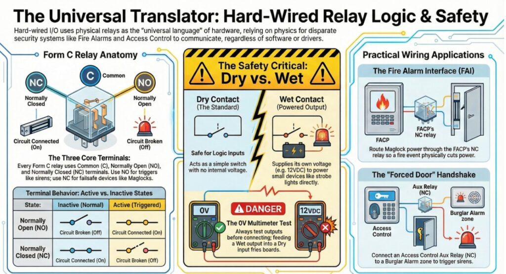
3. Form C Relays: The Standard
Almost every security device (Camera, Controller, Motion Sensor) has a “Relay Output” or “Alarm Output.” These are typically Form C Relays.
They have three terminals:
- C (Common): The entrance. This is where you put your wire coming in.
- NO (Normally Open): The “Off” state. The circuit is broken. It only connects to Common when the relay is active.
- NC (Normally Closed): The “On” state. The circuit is connected. It breaks connection when the relay is active.
The Logic:
- Triggering a Siren: Use NO.
- Normal: Circuit open. Silence.
- Active: Circuit closes. Power flows to siren. Scream.
- Holding a Maglock: Use NC.
- Normal: Circuit closed. Power flows to lock. Door locked.
- Active: Circuit opens. Power cut. Door unlocks.
4. Dry vs. Wet Contacts
This is the #1 way technicians blow up boards.
A. Dry Contact (The Standard)
- Definition: Just a switch. No electricity comes out of the terminals.
- Usage: You are just “shorting” two wires together for the other system.
- Example: Pushing an elevator button. You aren’t powering the elevator; you are just closing a circuit to tell the elevator controller to move.
B. Wet Contact (Powered Output)
- Definition: The terminal outputs Voltage (e.g., 12VDC) when triggered.
- Usage: To power a small device directly (like a strobe light or sounder).
- The Danger: If you connect a Wet Output (12V) from a Camera into the Dry Input of an Access Panel, you will feed 12V directly into a sensitive logic chip and fry the board.
- Field Test: Always put a multimeter on the output terminals before connecting wires. If you see voltage, it is Wet. If you see 0V (but continuity changes), it is Dry.
5. Practical Application: The “Forced Door” Integration
Scenario: You have an Access Control System (ACS) and a separate Burglar Alarm (IDS). You want the Burglar Alarm to scream if someone forces open the back door.
The Hardware:
- ACS Controller: Has an “Aux Relay” mapped to the “Forced Door” event.
- IDS Panel: Has a Zone Input available (Zone 5).
The Wiring:
- At the IDS (Input): Wire Zone 5 and COM to a cable.
- At the ACS (Output): Connect the other end of the cable to C (Common) and NC (Normally Closed) on the Aux Relay.
- Why NC? Because Alarm Zones expect a closed loop (Lesson 5.1).
- The Logic:
- Normal: The ACS relay is closed. The IDS sees a closed loop. (Zone Secure).
- Event: Burglar kicks door. ACS detects “Forced Door.” ACS fires relay (Opens it).
- Result: IDS sees the loop break. IDS triggers the siren.
6. The Fire Alarm Interface (FAI)
This is the most critical I/O integration in the building.
- Requirement: When the Fire Alarm (FACP) goes off, all Maglocks must cut power instantly.
- The Hardware: The FACP provides a Dry Contact relay that opens during a fire.
- The Wiring: You route the Power Wire (Positive leg) of your Maglock power supply through the FACP relay.
- Power Supply (+) -> FACP (Common).
- FACP (NC) -> Maglock (+).
- Operation:
- Normal: Relay is closed. Power flows through FACP to lock.
- Fire: FACP relay opens. The power wire is physically cut. The lock drops.